
Ingenico Telium Setup Guide
Description: Review how to set up an Ingenico Telium device below.
For information on the more recent model, the Ingenico TETRA, visit the Ingenico TETRA Setup Guide article.
Identifying Hardware and Configuration

To set up your new Ingenico device, you will need to identify three things before you begin. The hardware type, the software version, and the communication method used for the device.
Modern Ingenico devices will have the model name printed on the device's face just below the screen (like the image above). Older models should have a manufacturing sticker on the back of the device with the model type.
After identifying this, you will need to identify the type of Ingenico software and its version. You can view the device software type and version on the Ingenico Copyright screen. This can be brought up by power cycling or resetting the Ingenico device.
| Model Type | Reset Procedure |
|---|---|
| iSC250/480: |
Press and hold the Clear (Yellow) and the Minus ( - ) keys until the device chirps
|
|
iPP320/350: iWL252/258: iCMP/iSMPv4: |
Press and hold the Clear (Yellow) and the Period ( . ) keys until the device chirps
|
Depending on the device model type, it might be displayed differently, but it will always be displayed in the same order. Should this screen pass too quickly, you can always power cycle the device again with no issues to gather this detail.
Taking a picture of this screen may make reviewing this detail a bit easier
Examples of the Ingenico Copyright Screen(s)
U.S. Retail Base Application (RBA)


Canadian (CPX)
.png?revision=1)
Now that you have the device model and the loaded software version, identify the communication method that this device will be using.
Most modern device providers preconfigure the hardware for the desired communication type. However, to validate this detail, the configuration will show the previously mentioned copyright screen on boot-up or re-boot.
- For U.S. (RBA) Devices, this detail shows on the last line as one of the following.
- Serial: 115200, 8, none, 1, none
- USB<>CDC
- Ethernet: Server, Static
- USB-Base (Bluetooth With Charging Station)
- Bluetooth Mode: (Active\Inactive) (Bluetooth With USB Dongle)
- For Canadian (CPX) Devices, this shows in the center of the screen in brackets.
- <RS232> (Serial)
- <USB-9600>
.png?revision=1)
If you are using a U.S. device with a black and white screen you will need to scroll down to view this detail.
To validate the above, you can always check the cabling attached to the device; it should have a converted connector like the ones pictured below.
.png?revision=1)
If there is no cable or you have a charging station, you may be using WiFi  or Bluetooth
  . Typically, there is an icon displaying the connection type at the top of the screen.
If the cabling doesn't match the hardware settings or is not on the desired communication type, you need to reconfigure the hardware device.
- If the Serial, USB, or Bluetooth device is configured to your liking after validating the steps in this section, skip to Configuring The Device Host PC.
- If the Ethernet or WiFi device is configured to your liking after validating the steps in this section, you will still need to assign a Static IP Address from the network to the device, so continue with Reconfiguring Device Hardware.
- Otherwise, continue with Reconfiguring Device Hardware to reconfigure your (RBA) device. If using a (CPX) device, skip to the Canadian (CPX) Devices in Reconfiguring Device Hardware.
Reconfiguring Device Hardware
U.S. Retail Base Application (RBA)
Regardless of the model or software version in use, the configuration of Ingenico devices is typically straightforward and rarely changes between the various (RBA) software builds.
- To begin, reboot your device and enter the Telium Access Code on the Ingenico Copyright screen.
- When on the Ingenico Copyright screen, press 2, 6, 3, 4, and Enter. Shortly after this, the device will ask you to either press the (+) Plus or (F) Function for the menu.
If your device is requesting to press (F) for Menu but your unit doesn't have a function key simply press (+) Plus instead.
If the device starts showing an idle screen (Ads) or displaying the message "This Lane Closed" you will need to reboot and try entering the access code again. The code, if entered correctly, will display the Functions menu.
Note: For certain models (ie: iSC250/480, IPP320/350, and iSMP4), when the device is on This Lane Closed screen, you can press the (+) Plus or (F) Function button (depending on the device model) 6 times rapidly to enter the configuration startup script that will take you through all of the network settings including Comm Type and everything under Ethernet Settings in the Communication Menu. While this may be a quicker way to enter the configuration menu, the menu structure is different and may not match the steps shown within this article.
Navigate to the TDA menu in this list to configure the device.
.png?revision=1)
To continue with your setup, please select your desired connection type instructions.
Note: Pushing Cancel refers to the red button on the PIN Pad.
For each of the following connection types,
- Press [0] for Configuration
- Press [0] again for communication
- Press [0] again for Comm. Type (may be listed as Select Comm. Type)
.png?revision=1)
At this point, please click on a connection type to continue with its setup.
Serial
- Press [0] again for Serial (this option may be listed as [1]).
.png?revision=1)
- Press [Cancel] when complete to return to the Communication menu
- Press [1] for Serial Settings. The Serial menu will appear as follows, with the first few options visible
.png?revision=1)
.png?revision=1)
- Select [Baud Rate] and then [Set] to [115200]. Press Enter to set.

- Press [Cancel] when complete to return to the Serial Settings menu.
- Select [Stop Bit] and then [Set] to Option 0 which sets the stop bit to “1.”
- Press Enter to set.

- Press [Cancel] when complete to return to the Serial Settings menu.
- Select [Bits Per Byte] and then [Set] to Option 1, which selects the bits per byte to "8".
- Press Enter to set.

- Press [Cancel] when complete to return to the Serial Settings menu.
- Select [Parity] and then [Set] to [None].
- Press Enter to set.

- Press [Cancel] when complete to return to the Serial Settings menu.
- Select [Flow Control] and then [Set] to [None].
- Press Enter to set.

- Press [Cancel] until the device will ask you to Save Settings and Reboot? Select Yes.

Continue to Configuring The Device Host PC to continue with your setup.
USB
- Press [4] for USB<>Serial Conversion. (OR [3] for RBA 15 and lower or UIA devices.)

- Press [Cancel] when complete to return to the Communication menu.
- Press [1] for Serial Settings.

- The Serial menu will appear as follows, with the first few options visible:

- Select [Baud Rate] and then [Set] to [115200].
- Press Enter to set.

- Press [Cancel] when complete to return to the Serial Settings menu.
- Select [Stop Bit] and then [Set] to Option 0 which sets the stop bit to “1.”
- Press Enter to set.

- Press [Cancel] when complete to return to the Serial Settings menu.
- Select [Bits Per Byte] and then [Set] to Option 1, which selects the bits per byte to "8".
- Press Enter to set.

- Press [Cancel] when complete to return to the Serial Settings menu.
- Select [Parity] and then [Set] to [None].
- Press Enter to set.

- Press [Cancel] when complete to return to the Serial Settings menu.
- Select [Flow Control] and then [Set] to [None].
- Press Enter to set.

- Press [Cancel] until the device will ask you to Save Settings and Reboot? (screen title may vary) Select Yes.

Continue to Configuring The Device Host PC to continue with your setup.
Ethernet
Before continuing with this section, it is important to verify the settings of the host computer.
- Open the command prompt by typing CMD after clicking on the Windows start button
- At the prompt, type ipconfig /all
- Information needed includes:
- DHCP Enabled (example: yes or no)
- IPv4 Address (for UTG “express” tab)
- Subnet Mask
- Default Gateway

- Press [1] for Ethernet. (Sometimes, this option can be listed as [2] depending on your RBA build.)

- Press [Cancel] when complete to return to the Communication menu.
- Press [0] for Communication.
- Press [2] for Ethernet Settings.

- Press [0] for the Connection Method and then select [1] for Server.

- Press [Cancel] when complete to return to the Ethernet Settings menu.
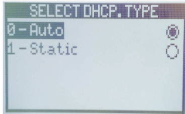
- Press [1] for DHCP to choose whether the IP address will be static or assigned by a DHCP Server

This is a determination that will need to be made by your IT or networking staff. If they are setting a static IP, they must ensure it is a unique IP address that is not in use on the network for each device. If they are using a DHCP assigned IP Address, they must ensure that they have a DHCP reservation set for the devices to ensure that it always receives the same IP Address from the DHCP Server. If the IP Address changes, the Universal Transaction Gateway will not be able to communicate with or control the device.
- Press [1] to set a Static IP (Preferred).

- Press [0] if the IP is handled via a router with DHCP enabled (Dynamic Host Configuration Protocol).

- Press [Cancel] when complete to return to the Ethernet Settings menu.
- Press [3] to set the IP address. Three digits must be entered for each octet, so an IP address of 10.0.1.193 would be entered as 010.000.001.193. In the following example, the PIN Pad’s address 10.17.29.7 is entered as 010.017.029.007 to include the leading zeros.
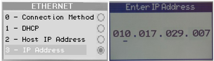.png?revision=1)
- Press [Cancel] when complete to return to the Ethernet Settings menu.
- Press [4] to enter the Subnet Mask. This is determined by property IT. Three digits must be entered for each octet, so an IP address of 255.255.255.0 would be entered as 255.255.255.000.

- Press [Cancel] when complete to return to the Ethernet Settings menu.
- Press [5] to set the Default Gateway. This IP address is determined by the property IT. Three digits must be entered for each octet, so a Default Gateway IP address of 10.0.1.1 would be entered as 010.000.001.001. In the following example, the Default Gateway IP address 10.17.29.1 is entered with leading zeros.
.png?revision=1)
- Press [Cancel] when complete to return to the Ethernet Settings menu.
- Press [9] to set the IP Port. The default port setting is 12000 though the property IT could choose to change this under rare circumstances.

- Press [Cancel] when complete to return to the Ethernet Settings menu.
- Use the PIN Pad's navigation controls to highlight option [11] for the SSL settings. (RBA 21+ only). This setting was added in RBA 21 and should always be set to no.

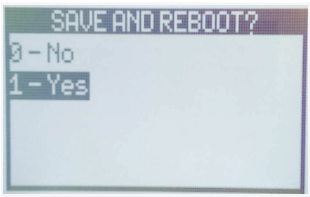
- Press [Cancel] until the device will ask you to Save Settings and Reboot? (screen title may vary) Select Yes.

Continue to Configuring The Universal Transaction Gateway to continue with your setup.
WiFi
Note: If the customer has already set up their WiFi network as "hidden," there is occasionally an issue with network registration where the device will be unable to connect to the network even if it has all of the correct information.
This may occur if the access point refuses first-time handshakes while hidden. The problem can typically be remedied by setting the network as discoverable for the initial device connection, then changing it back to hidden once the device has successfully connected.
- Press [2] for Ethernet (for some versions, this may be [1]).

- Press [Cancel] when complete to return to the previous menu.
- Press [4] for WiFi Settings.

- Press [1] for Boot Protocol To choose whether the IP address will be static or assigned by a DHCP Server.
Note: This is a determination that will need to be made by your IT or networking staff. If they are setting a static IP, they must ensure it is a unique IP address that is not in use on the network for each device. If they are using a DHCP-assigned IP Address, they must ensure that they have a DHCP reservation set for the devices to ensure that it always receives the same IP Address from the DHCP Server. If the IP Address changes, the Universal Transaction Gateway will not be able to communicate with or control the device. - Press [1] to set a Static IP (Preferred).

- Press [0] if the IP is handled via a router with DHCP enabled (Dynamic Host Configuration Protocol).
- Press [Cancel] when complete to return to the previous menu.
- Press [2] to set the IP address. Three digits must be entered for each octet, so an IP address of 10.0.1.193 would be entered as 010.000.001.193. In the following example, the IP address 10.17.29.7 is entered as 010.017.029.007 to include the leading zeros.

- Press [Cancel] when complete to return to the previous menu.
- Press [3] to enter the Subnet Mask. This is determined by property IT. Three digits must be entered for each octet, so an IP address of 255.255.255.0 would be entered as 255.255.255.000

- Press [Cancel] when complete to return to the previous menu.
- Press [4] to set the Default Gateway. This IP address is determined by the property IT. Three digits must be entered for each octet, so an IP address of 10.0.1.193 would be entered as "010.000.001.193".

- Press [Cancel] Until the device asks you to Save Settings and Reboot? Select Yes.

- During reboot, when on the Ingenico Copyright screen, press 2, 6, 3, 4, and Enter to re-access the Functions Menu.
- Press [0] for TELIUM MANAGER.

- Press [3] for Initialization.
- Press [2] for Hardware.

- Press [5] for WiFi setup (if available).

- Press [1] for Profiles

- Press [1] for New Profile (this may be displayed as Profiles).
[Option 1] Automatic Scan
- Press [1] Automatic Scan to pair the device to your WiFi network. Select your WiFi network from the list and configure it by completing the following steps:
- Select the Security Type
- Select the Cypher. - The highest level of encryption is recommended
- Enter your WiFi password
- Enter the Priority. - If configuring the device for multiple WiFi networks, it will connect to them in the priority order
- Press [Cancel] Until the device will ask you to Save Settings and Reboot? Select Yes
[Option 2] Manual Connection
- Press [2] – Manual Connection if not found on the profile menu and complete the following steps:
- From the hidden access point?
- Select [1] – No; if not hidden
- Select [2] – Yes; if hidden
- Enter your WiFi Network Name
- Select the Cypher. - The highest level of encryption is recommended
- Enter your WiFi password
- Enter the Priority. - If configuring the device for multiple WiFi networks, it will connect to them in the priority order
- Press [Cancel] Until the device will ask you to Save Settings and Reboot? Select Yes
Continue to Configuring The Universal Transaction Gateway to continue with your setup.
Bluetooth (w/USB Charging Station)
Note: Any devices that come packaged with a Charging Station must be seated in the station while the device menus are being accessed. Otherwise, the device will power off during operation. This is a built-in security feature with mobile models and can not be turned off.
- Press [5] for USB<>Smart Base.
- Press [Clear/Cancel] when complete to return to the Communication menu.
- Press [1] for Serial Settings.

- The Serial menu will appear as follows, with the first few options visible:

- Select [Baud Rate] and then [Set] to [115200]. Press Enter to set.

- Press [Cancel] when complete to return to the Serial Settings menu.
- Select [Stop Bit] and then [Set] to Option 0 which sets the stop bit to “1”.
- Press Enter to set.

- Press [Cancel] when complete to return to the Serial Settings menu.
- Select [Bits Per Byte] and then [Set] to Option 1, which selects the bits per byte to "8".
- Press Enter to set.

- Press [Cancel] when complete to return to the Serial Settings menu.
- Select [Parity] and then [Set] to [None].
- Press Enter to set.

- Press [Cancel] when complete to return to the Serial Settings menu.
- Select [Flow Control] and then [Set] to [None].
- Press Enter to set.

- Press [Cancel] until the device will ask you to Save Settings and Reboot? Select Yes.
- Put the device on the smart base
- During reboot when on the Ingenico Copyright screen press 2, 6, 3, 4, and Enter to access the Functions Menu
- Select the TSA Menu
- Press [0] for TELIUM MANAGER
.png?revision=1)
- Press [3] for Initialization
- Press [2] for Hardware
.png?revision=1)
- Press [4] for Cradle Setup
- Press [1] for Association
- Press [1] for New Base
- The device will synchronize with the base it is currently on.
- Put the device on the smart base.
- Press the upper left 'F' button 4 times quickly.
- After a few seconds, the device should beep twice.
- The device will synchronize with the base it is currently on.
Bluetooth (w/USB Dongle)
- Press [2] for Bluetooth
- Press [Clear/Cancel] when complete to return to the Communication menu
- Press [1] for Bluetooth Settings
- Press [?] for Pair
- Press [Cancel] Until the device will ask you to Save Settings and Reboot? Select Yes
Continue to Configuring The Device Host PC to continue with your setup.
Canadian (CPX) Devices
Begin by rebooting the device.
For iPP320: Press and hold the Clear (Yellow) button and the Period ( . ) keys.
.png?revision=1)
When the device boots to the screen showing the (CPX) version, the (?) character will be displayed for a few seconds at the bottom.

Note: The device’s CPX version should be CPX07.69 or CPX09.06. If the device displays another CPX, the merchant must speak to their device vendor to obtain a device on CPX07.69 or CPX09.06, as any other version will not work as intended. We only support two CPX versions for Canadian devices, Telium 7.69 or Tetra 09.06.
- Press the Green (enter) button while the (?) is displayed.
- Press F4 to cycle through the menu options.
- Press the Yellow (clear) button to change the setting on an option.
- Press the Green (enter) button to save your changes.
- Select Com Port, then select USB 9600 for a USB device or RS232 for a Serial device.
- You can now save the set-up and reboot the device.
Continue to Configuring The Device Host PC to continue with your setup.
Configuring The Device Host PC
If using Ethernet or WiFi skip to Configuring The Universal Transaction Gateway.
If you are using Serial, USB, or Bluetooth you will need to configure the Local PC Host Environment, and depending on the Windows OS version and the presence of the Shift4 UTG Software this can change the device setup process.
Windows Device Manager
Note: All USB connection types on Windows 8.1 or lower will require a USB driver so that the hardware can speak to the Shift4 Universal Transaction Gateway or UTG Stub controller.
Details regarding downloading the driver and its installation can be found here, USB Driver Installation for Ingenico.
Once this is installed or if on Windows 10 you can configure the Windows Device Manager. For instructions on accessing Device Manager in various Windows Operating Systems See, Accessing the Windows Device Manager.
Once In the Device Manager, click the arrow next to Ports (COM & LPT), then right-click where the Ingenico device is connected and select Properties.
- In Window 8.1 and lower with the Jungo Driver, this will be named Ingenico [MODEL] Comm Port.
- In Windows 10, this will show as USB Serial Device.
_(1).png?revision=1)
.png?revision=1)
Select the tab labeled Port Settings.
_(1).png?revision=1)
The Port Settings tab will display the Baud rate (Bits Per Second), Data Bits, Flow Control, Parody, and Stop Bits settings. Match these settings to those configured for the device in the previous section, which should match the table(s) below for your device type.
_(1).png?revision=1)
- In the Advanced Settings for Windows 8.1 or lower, you only need to configure the desired COM Port.
- In the Advanced Settings for Windows 10 ensure that the FIFO Buffers are disabled (unchecked) and that the desired COM Port is configured.
Note: If 'Advanced Settings' on the Port Setting screen is 'grayed-out' you will need to get your IT involved to get Admin access to the PC to set this value.
Installing and Configuring The UTG Stub
To learn how to Install, Configure and Troubleshoot the Stub refer to this article.
Configuring The Universal Transaction Gateway
You will now need to configure the Universal Transaction Gateway (UTG) TuneUp. To access the UTG (v2) TuneUp the UTG services or UTG Stand Alone must be stopped first.
Note: Stopping the Universal Transaction Gateway (UTG) service or Stand Alone will stop all active credit card processing until it is restarted. Instructions for starting, stopping or restarting a Shift4 Service can be found here, Starting/Stopping a service in Windows including UTG Service, UTG Stub, and 4Go. Instructions for closing the UTG (v2) Stand Alone can be found here, Starting and Stopping the UTG (v2) Stand Alone.
To open the Universal Transaction Gateway (UTG) TuneUp got to Start > All Programs > Shift4 Payments > UTG (v2) TuneUp. If this is missing from your Windows Start Menu see, How to Access the Shift4 UTG (v2) TuneUp.
In the Universal Transaction Gateway (UTG) TuneUp, navigate to the Devices tab. If working on a new device, click Add. If working on an existing device, locate the device, select it, and click Edit. Determine the following.
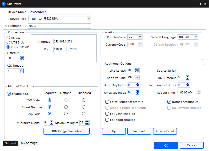
Required Settings:
- Device Name enter a unique name that will identify where the device is located.
- Device Type should be chosen according to the model of the device and loaded software (RBA or CPX) the device is using (This information should have been collected in Section 1)
- API Terminal ID is the Terminal ID that is being sent by the interface to 'wake' the device. This must be entered identically to how it appears in the interface setup or the device will never activate.
- Terminal ID's Must Be Unique and can not be blank. If you do not know this detail simply set a value as it can be changed later.
- Source Serial is the Shift4 Account or Serial Number where the EMV Device Settings are stored in Lighthouse Transaction Manager.
- If this setting is not set, EMV Terminal Downloads will default to whatever Shift4 Serial is set as the Serial Number in the Express Tab within the UTG (v2) TuneUp
- Connection: This is the connection type that should be selected for the connected PIN-pad
Optional Settings
Note:Additional Options are only provided based on the hardware capabilities. If your selected device model isn't showing an option listed here it's possible the chosen hardware doesn't support this additional feature.
- Manual Card Entry determines if you wish to allow Manual Card Entry (MCE) via this device. If so, you should enable the checkbox for Enable MCE and select their desired CVV Code, Street Number, and Zip Code settings (Required, Optional, or Disabled.)
- BIN Range Overrides determines if you wish to bypass specific card validations during manual entry for certain card types like Gift Cards. Example: bypass CVV, AVS, or Expiration
- Contactless Enabled allows you to accept RFID-based transactions such as Google Wallet or Apple Pay
- Bypass Amount OK allows you to disable the amount OK screen
- Cashback allows the setup of predetermined thresholds to have cash returned on purchase
- Tip allows US RBA Devices to enable tip prompting during checkout
For other settings not listed here, it is best to speak to a Shift4 Support Agent to identify and configure additional hardware features for your setup.
Select OK once all options and requirements are completed to save the settings. Repeat this step for each device you have set up.
Once all devices are added and set up, select Save at the top of the UTG (v2) TuneUp. It will close and you can now restart your Universal Transaction Gateway Services or Stand Alone.
Test a transaction from the Interface to validate communication at this time.